Mon - Fri 8:00AM - 5:00PM Central
1150 SE Hamblen Rd, Lee's Summit, MO 64081
Selecting the right Fanuc Encoder is no longer a simple replacement task. Global buyers must compare resolution, mounting style, feedback protocol, shaft design, and machine compatibility. A small mismatch can cause unstable positioning, alarm codes, or repeated downtime.
Fanuc servo motors may use incremental or absolute feedback systems. Some applications require optical sensing, while harsh workshops may demand stronger sealing and vibration resistance. The connector also matters. Dust, oil mist, and cable bending can damage an otherwise suitable unit.
“Encoder accuracy is valuable only when the entire feedback chain remains reliable,” says Hiroshi Tanaka, a veteran FANUC motion-control specialist. His point deserves attention. Many purchasing errors begin with a part number copied from an old label. That approach is fast, but not always safe.
This 2026 guide compares the leading Fanuc Encoder types for international buyers. It examines A860-series feedback devices, compatible motor applications, signal formats, resolution ranges, and practical sourcing concerns. Readers will also find guidance on original, refurbished, and replacement options.
Check the manual carefully.
A genuine encoder may still fail if its parameter settings are wrong. Conversely, a tested replacement can perform well when specifications match precisely. That is where product history, inspection records, and supplier competence become important.
The market is not perfectly consistent. Catalog descriptions sometimes omit connector details or revision differences. Buyers should verify motor model, encoder code, interface, and installation conditions before ordering. This guide offers a practical starting point, not a substitute for manufacturer confirmation.
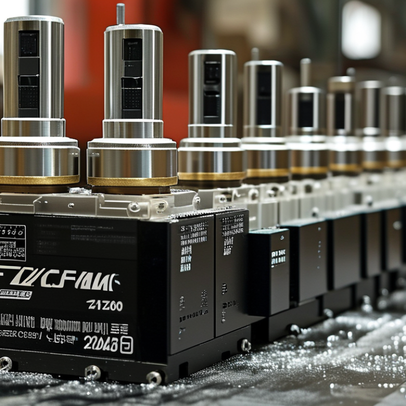
A FANUC encoder is a feedback device mounted on a servo motor or machine axis. It measures shaft position, speed, and rotational direction. The controller uses this information to coordinate accurate movement, even during rapid acceleration or deceleration.
Many FANUC encoder types use optical sensing. A coded disk passes through a light path, creating electrical pulses as the motor turns. Incremental models report movement from a reference point. Absolute models retain a unique position value, which helps the machine recover its location after power loss. Some systems transmit serial data instead of simple pulse signals. The exact interface depends on the motor and controller design.
A practical maintenance check begins with the connector, cable shield, and shaft coupling. Loose pins can create intermittent position alarms that look like encoder failure. Dust, heat, and vibration also matter. Small errors become visible.
Technicians should compare alarm records with commanded and actual positions. They should also verify grounding and cable routing before replacing parts. A replacement encoder may fit physically but still require correct parameters or calibration. That detail is easy to miss. In real workshops, troubleshooting is not always clean; a damaged cable can imitate a sensor fault, while a poorly aligned coupling can produce unstable readings. Reliable work depends on the machine manual, measured evidence, and careful testing.
Industrial encoder selection starts with motion requirements, not catalog labels. Incremental rotary encoders generate pulses as a shaft turns. They suit spindle feedback, conveyor positioning, and general speed control. Their signals are simple and cost-effective. However, the controller may lose position after power interruption.
Absolute rotary encoders retain position through power cycles. They are useful for servo axes, robotic joints, and indexing tables. Multi-turn versions track several revolutions, which benefits long-travel mechanisms. Linear encoders measure movement directly along a guideway. They support high-precision machine tools where ballscrew error or thermal expansion can affect accuracy. The real-world choice depends on resolution, repeatability, and communication protocol.
In field servicing, I check shaft coupling, mounting space, cable routing, and contamination risk before approving an encoder. A dusty cutting area needs stronger sealing than a clean assembly station. Confirm the supply voltage and output interface with the controller. Also verify connector orientation and cable length. Small mismatches create unstable feedback.
Do not chase resolution alone.
For global buyers, compare operating temperature, vibration tolerance, protection rating, and replacement availability. Incremental units often simplify maintenance. Absolute units can reduce homing procedures. Linear devices may deliver better accuracy, but alignment becomes more demanding. I have seen technically excellent selections fail because installers ignored grounding or coupling flexibility. Datasheets help, yet actual machine conditions deserve equal attention.
This chart compares common encoder technologies by their typical suitability for industrial motion-control applications. Incremental rotary encoders are widely used for speed and position feedback, absolute rotary encoders retain position information after power loss, linear encoders provide direct axis measurement, and resolver-based feedback is valued in demanding industrial environments. Scores are normalized engineering reference values, not market-share data.
For global buyers, encoder selection should begin with the motion requirement, not the catalogue headline. Resolution describes position steps, while accuracy shows how closely those steps match the real shaft angle. A 20-bit encoder offers over one million counts per revolution, but mechanical runout, temperature, and interpolation can reduce useful accuracy. Higher resolution is not automatically better.
The International Federation of Robotics reported 541,302 industrial robots installed worldwide in 2023, a 2% annual increase. This growth raises demand for stable feedback in joints, conveyors, and precision stages.
Buyers should request accuracy in arc-seconds, repeatability data, and test conditions. Check the full temperature range.
Signal output also affects machine performance. Differential digital outputs resist electrical noise across long cables.
SSI or BiSS interfaces can provide absolute position data, while analog sin/cos signals support high interpolation rates. Confirm voltage levels, cable length, update frequency, and controller compatibility before ordering. Small details matter.
In practical testing, compare encoder feedback against a calibrated reference table. Watch for missed counts during rapid reversal.
I have seen impressive resolution figures hide weak installation tolerances. That deserves careful reflection.
Industry market analyses from MarketsandMarkets also identify automation and robotics as major encoder demand drivers, but forecasts vary by region and application. Treat projections as planning evidence, not guaranteed purchasing facts.
Choosing the right industrial encoder starts with the machine, not the catalog. Map the motor, feedback loop, controller interface, shaft size, and mounting space. For position retention after power loss, absolute encoders often fit better than incremental units. They can cost less. However, resolution alone is not accuracy. Thermal drift, backlash, cable noise, and installation errors can dominate the final result. Measure twice.
The International Federation of Robotics reported 541,302 industrial robot installations worldwide in 2023, with Asia representing about 70% of deployments. This scale increases demand for dependable feedback in robots, machine tools, and handling systems. It does not justify choosing the most expensive sensor. Buyers should compare resolution, repeatability, response speed, operating temperature, and service availability. A technically advanced encoder may still be a poor choice when local replacement support is weak.
For global equipment, confirm protocol compatibility before placing an order. Check connector standards, cable lengths, ingress protection, vibration tolerance, and regional documentation. A dusty machining cell may require stronger sealing than a clean assembly line. Field experience shows that a perfect specification can still fail during installation. Documentation may be incomplete. Ask suppliers for interface drawings, test records, and lifecycle data, then match those details against the controller manual. The MarketsandMarkets 2024 encoder analysis identifies automation and motion control as key market drivers, but growth does not remove selection risk. A matching spare and clear wiring guide can prevent costly downtime.
| Encoder Type | Feedback Method | Typical Resolution | Output / Interface | Position Information | Common Mechanical Form | Typical Operating Range | Best-Fit Application | Global Buyer Selection Check |
|---|---|---|---|---|---|---|---|---|
| Incremental Optical Rotary Encoder | LED and code disk generate pulse trains | 500–10,000 pulses per revolution; quadrature can provide 2x or 4x counting | A/B quadrature, often with an index Z channel; differential line-driver output is common | Relative position; reference return is normally required after power loss | Solid-shaft or hollow-shaft rotary body | Typically about −20°C to +85°C, depending on construction | General servo feedback, speed monitoring, conveyors, and retrofit motion systems | Confirm pulse frequency, supply voltage, A/B phase sequence, index position, and cable shielding |
| Incremental Magnetic Rotary Encoder | Hall-effect or magnetoresistive sensing of a magnetic target | Typically 256–4,096 pulses per revolution | A/B quadrature, with optional index; push-pull or differential output depending on model | Relative position and rotational speed | Compact hollow-shaft or modular board-mounted design | Often about −40°C to +105°C for industrial-rated versions | Applications exposed to dust, vibration, oil mist, or moderate contamination | Check magnetic-field exposure, air gap, shaft runout, electrical noise immunity, and sealing level |
| Single-Turn Absolute Optical Encoder | Coded optical disk provides a unique digital angle value | 12–22 bits per revolution, equivalent to 4,096–4,194,304 positions | Serial digital interface or parallel output; protocol is model-specific | Absolute angle within one revolution; retained through power interruption | Flange-mounted, solid-shaft, or hollow-shaft assembly | Commonly about −20°C to +100°C | Robotic joints, indexing tables, precision axes, and machines requiring fast restart | Match the communication protocol, data frame, resolution, direction setting, and controller firmware |
| Multi-Turn Absolute Optical Encoder | Absolute optical angle measurement combined with revolution counting | Typically 17–25 bits per turn; multi-turn range may cover several thousand revolutions | Serial digital communication; battery-backed or gear-based multi-turn storage may be used | Absolute position across multiple revolutions | Robust rotary housing with precision bearings and shaft coupling | Often about −40°C to +85°C; confirm battery limits where applicable | Long-travel machine axes, lifting systems, rotary positioning, and large-format equipment | Verify multi-turn technology, backup-power requirements, maximum travel, and homing strategy |
| Sine-Cosine Rotary Encoder | Sinusoidal analog signals interpolated by the drive | Commonly 1,024–5,120 sine-wave cycles per revolution before interpolation | Differential 1 Vpp sine and cosine signals, frequently with a reference mark | Relative position with high interpolation capability | Precision rotary encoder with solid or hollow shaft | Typically about −10°C to +100°C | High-speed servo axes and applications requiring smooth velocity feedback | Check signal amplitude, impedance, cable length, interpolation factor, and analog bandwidth |
| Rotary Resolver | Transformer-based electromagnetic angle measurement | Typically 10–16 electrical bits after digital conversion | Analog sine/cosine resolver signals requiring a compatible resolver interface | Relative angular position; reference behavior depends on the drive system | Highly robust brushless rotary transformer construction | Often about −55°C to +155°C in specialized industrial designs | High-temperature, high-vibration, or electrically harsh environments | Confirm excitation frequency, transformation ratio, phase accuracy, resolver interface, and alignment |
| Linear Incremental Encoder | Optical or magnetic scale produces position pulses along a linear axis | 10–100 micrometres signal pitch; final resolution depends on interpolation | A/B quadrature with optional reference marks; differential signaling is common | Relative linear position; homing or reference marks are normally required | Exposed or enclosed readhead-and-scale system | Typically about −10°C to +70°C; precision systems may require thermal control | Machine tools, linear stages, and axes where ballscrew error compensation is important | Check scale length, mounting tolerance, reference-mark layout, contamination protection, and thermal expansion |
| Linear Absolute Encoder | Coded optical or magnetic scale provides a unique linear position | Typical resolution from 0.1 to 5 micrometres | Serial digital output or manufacturer-specific absolute protocol | Absolute linear position after power-up, subject to interface initialization | Sealed linear scale with separate scanning head | Commonly about −20°C to +70°C | Precision positioning, semiconductor handling, metrology, and automated production equipment | Confirm absolute protocol, measuring length, accuracy grade, installation orientation, and thermal compensation |
Installation, compatibility, and maintenance determine encoder performance more than specifications alone. Incremental encoders suit many standard motion systems and provide reliable speed feedback. Absolute encoders retain position data after power loss. Serial feedback models reduce wiring but require matching communication settings. Resolver-based units can tolerate heat and vibration, though their signal conditioning needs careful checking.
Measure the original encoder before ordering. Confirm shaft diameter, mounting holes, connector position, resolution, supply voltage, and output type. Small differences matter. Check the controller’s feedback protocol and required counting direction.
During installation, isolate power and protect the sensor from static discharge. Align the coupling without side pressure. Never force a connector into place. Secure cables away from motor leads, sharp edges, and moving assemblies.
Maintenance should include visual checks for dust, oil, loose fasteners, and cable damage. Listen for unusual servo noise. Review diagnostic values before changing parts. Excessive following error may indicate misalignment, wiring faults, or a failing sensor. Keep the parameter backup beside the machine, not only on one technician’s computer. Replacement work is not always clean. A new encoder can expose an old grounding problem. Record the installed resolution and zero position after testing. Recheck these notes after the first production shift.
