How to Choose the Right Optical Attenuator?
Choosing the right Optical Attenuator begins with understanding the system around it. A fiber link may need controlled signal reduction, but the correct device depends on wavelength, connector type, power level, and required attenuation. A component suitable for 1310 nm may not perform equally at 1550 nm. Small differences matter.
Experienced technicians usually check the transmitter output before selecting an attenuator. They also measure the receiver’s acceptable input range. For example, a 10 dB device can prevent overload, but excessive attenuation may weaken the signal below its reliable operating threshold. Variable attenuators offer flexibility during testing, while fixed models often provide better consistency in permanent installations. Always confirm compatibility with single-mode or multimode fiber.
Testing should not stop at the product label. Inspect the connectors for dust, scratches, or loose fittings. Then measure insertion loss with calibrated equipment under realistic operating conditions. Manufacturer data is useful, but field results can differ. No selection method is flawless. Even experienced engineers can overlook temperature changes or connector wear. That is why documented measurements, recognized technical standards, and supplier support remain valuable.
A reliable choice balances optical performance, installation conditions, budget, and future maintenance. The cheapest Optical Attenuator may create hidden costs through unstable links or repeated troubleshooting. A careful evaluation provides stronger evidence than assumptions. It also helps teams select components that remain dependable as networks expand, upgrade, or face changing transmission demands.
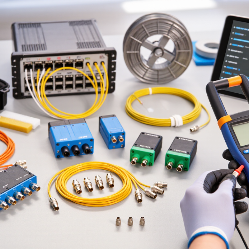
What an Optical Attenuator Is and How It Works
An optical attenuator is a passive device that reduces optical power in a fiber link. It protects receivers from signals that are too strong. It also helps engineers create a controlled power level during testing. In simple terms, it works like a dimmer for light traveling through fiber. The device introduces a known amount of loss, measured in decibels (dB).
An attenuator may absorb, scatter, or reflect part of the optical signal. Fixed models provide one stable loss value, while variable models allow field adjustment. The correct choice depends on wavelength, connector type, power range, and required attenuation. A 10 dB attenuator does not simply make the signal “a little weaker.” It reduces optical power to one-tenth of its original level. Small details matter.
In practical testing, check insertion loss and return loss with suitable measurement equipment. Confirm that the attenuator can handle the expected input power without overheating or distorting results. I have seen troubleshooting become harder when technicians ignore connector cleanliness. Dust can imitate excessive loss. Real installations are less tidy than laboratory diagrams. That matters. It is also wise to verify the actual attenuation after installation, because tolerances, adapters, and aging can change the measured result. A specification sheet helps, but it cannot replace a measurement taken at the working wavelength.
Identify the Right Attenuator Type for Your Fiber Application
How to Choose the Right Optical Attenuator?
Choosing an optical attenuator starts with the fiber application, not the connector. A fixed attenuator suits stable links. Use a variable attenuator during commissioning, testing, or changing power conditions. Inline units fit patch-cord paths, while bulkhead designs save panel space. That sounds simple. For single-mode links, verify the operating wavelength and connector polish. Multimode systems require compatible components and a clearly stated attenuation range.
Do not select by dB alone. Receiver sensitivity, transmitter output, power rating, return loss, and insertion loss must be checked together. IEC 61300-3-4 defines methods for measuring insertion loss. IEC 61300-3-6 addresses return loss. These measurements reveal a common problem: a nominal 10 dB attenuator may perform differently across wavelengths. Clean connectors matter too. Dust can create unstable readings and misleading loss values. I have seen technicians replace a component before inspecting the adapter.
Network growth makes accurate optical budgets more important. ITU’s Facts and Figures 2023 reported 5.4 billion people online. The Cisco Annual Internet Report projected 29.3 billion networked devices by 2023. More traffic demands repeatable testing and documented margins. Measure power at the receiver, then compare it with the equipment specification. Leave practical engineering margin. Record results at the actual wavelength. The perfect choice is not always obvious, and that uncertainty deserves a second measurement.
Assess Connectors, Performance, and Environmental Conditions
How to Choose the Right Optical Attenuator?
Connector selection should begin with the installed fiber system. Match the attenuator’s connector polish, alignment sleeve, and end-face geometry. An APC connector should not be joined casually with a UPC connector. The mismatch can increase reflections and disturb sensitive receivers. IEC 61300-3-34 specifies connector attenuation measurement methods, while ITU-T G.671 covers optical component characteristics across common telecom wavelengths. These references provide a stronger basis than catalogue claims.
Performance must be checked at the operating wavelength, not only at 1550 nm. Measure insertion loss, return loss, power handling, and attenuation tolerance. A nominal 10 dB attenuator may not deliver exactly 10 dB under every temperature. In field testing, clean connectors matter greatly. Dust can create unstable readings, especially around high-density patch panels. Keep inspection records.
Environmental conditions often expose weak choices. Check the rated temperature range, humidity, vibration, and storage limits. IEC 61753 performance categories help classify environmental reliability. Outdoor cabinets may face condensation, while indoor racks can experience repeated thermal cycling. I have seen teams select by attenuation alone, then revisit the choice after thermal drift appeared. That shortcut is understandable, but incomplete. Consider connector access and cleaning space too. A compact part may save rack space yet complicate maintenance.
Verify System Compatibility Before Making the Final Choice
How to Choose the Right Optical Attenuator?
Verify System Compatibility Before Making the Final Choice
Choosing an optical attenuator starts with system compatibility, not attenuation value alone. A device may provide the correct loss but still weaken the entire link.
Check the operating wavelength first. Common fiber systems use 1310 nm, 1490 nm, or 1550 nm signals. The attenuator should support the exact range used by your equipment. Confirm connector type, fiber mode, and polished end-face requirements. A mismatch can create unexpected reflection or unstable readings.
Review the power rating carefully. Measure the transmitter’s actual output, then compare it with the attenuator’s maximum input power. Leave a reasonable safety margin. Also inspect insertion loss, return loss, and attenuation tolerance. These specifications matter during commissioning and fault testing.
I usually connect the attenuator to a calibrated power meter before installation. This simple check can reveal a surprising difference between the labeled value and the measured result. I once focused on attenuation and overlooked connector cleanliness. The readings drifted until the end faces were inspected and cleaned. That mistake was avoidable.
Test the complete path, not only the component. Record power levels at both ends and repeat the measurement after reconnecting the cables. Small changes may expose a poor fit. No checklist is perfect. Still, careful verification reduces rework and protects sensitive optical receivers.
